



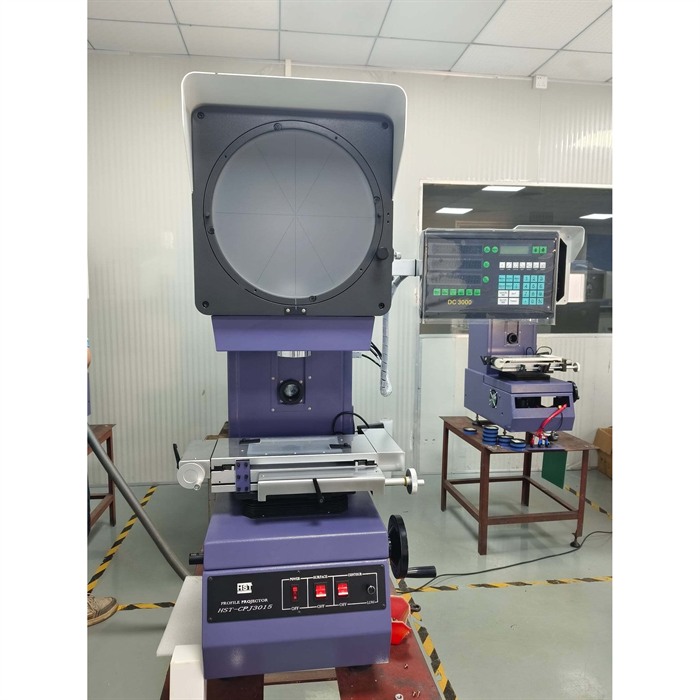
KASON CPJ3015 is a vertical profile projector in the optical profile projector range, and its job is different from that of a caliper. A caliper returns a number and hides everything else. A projector throws a magnified silhouette of the part onto a screen, so the flank of a thread, the radius at the root of a fillet and the flat worn on a crest are visible at the same time as the dimension that describes them. That difference matters most when a part is rejected and nobody can say why: on a screen, the reason is a shape, not an argument.
Key Takeaways
- A profile projector measures a silhouette, so it is strongest on parts whose function is defined by their outline: threads, form tools, cams, small stampings and profiles.
- Transmitted light shows the outline, reflected light shows the surface; a single part usually needs both before an opinion is formed.
- The digital readout turns table travel and screen rotation into numbers, but the screen is what tells you whether those numbers describe the feature you think you are measuring.
- Thread work is judged against a basic profile, and the basic profile differs between the metric and the unified systems even though both use a sixty degree flank.
- Pass or fail is a decision about conformity, not a comparison of two numbers, which is why the decision rules in ISO 14253-1 matter as much as the measurement itself.
The Silhouette Principle
The projector sends light through the part and images its outline onto a screen through an objective. Because the image is a projection rather than a photograph, the edge stays sharp over the whole field, and a part that is thinner than the depth of focus still reads correctly at its widest section. That is why the technique suits turned and ground parts with a defined cross section, and why it is a poor choice for a soft or burred edge that collapses under the light.
Reflected illumination is the other half of the instrument. With the light thrown onto the surface instead of through the part, the screen shows what the transmission view cannot: a die mark, a grinding direction, a chipped crest or the difference between a rounded root and a sharp one. A thread that looks perfect in silhouette often reveals a torn flank in reflection, and the torn flank is what fails in service.
What the Screen Actually Lets You Measure
Length and diameter are the easy answers, and they are the ones a buyer thinks about first. The features that justify the instrument are the others: the included angle of a thread, the half angle of each flank, the pitch measured along the axis, the radius at the root, the angle of a chamfer, the straightness of an edge, the concentricity of two diameters when the part is rotated on the screen, and the profile of a form tool that has been reground until its shape no longer matches the drawing.
Radius and angle are where the projector earns its place. A radius gauge is a guess confirmed by eye; on a screen with a chart overlay, the radius is compared against a known arc drawn to scale, and the deviation is visible before any number is written down. The same applies to a cam profile or a template, where the question is not one dimension but whether the whole curve stays inside its tolerance band.
Threads: Two Systems, One Screen
Thread measurement is the classic projector job, and it is also where the most mistakes are made, because the two dominant thread systems look alike and are not alike. ISO 68-1 defines the basic and design profile of ISO general purpose metric threads: the symmetrical sixty degree form, the truncation at the crest and the root, and the proportions that follow from the pitch rather than from the diameter. ASME B1.1 covers the unified inch threads, including the UN, UNR and UNJ forms, where the same nominal flank angle coexists with different root practice and, in the J form, a controlled root radius that exists specifically to survive fatigue.
The practical consequence is that a chart or overlay cut for one system will pass a part that the other system would reject, and the difference sits in the root, which is exactly the region a silhouette shows best. This is why the drawing has to be read before the overlay is chosen, and why a projector with a rotating screen and a set of charts is more useful than a fixed reticle: the angle is set to the part, the part is not forced to the angle.
From Screen to Number: the Readout
The digital readout converts table movement into coordinates and screen rotation into angle, and it does the arithmetic that used to be done by hand: the difference between two edges, the centre of a circle from three points, the angle between two lines, the distance between centres. Its real value is repeatability. Two inspectors measuring the same part will place an edge slightly differently, but if the edge is captured the same way both times, the readout removes the arithmetic disagreement and leaves only the judgement about where the edge is.
That judgement is why the accessories matter more than they appear on a specification sheet. A foot switch frees both hands to hold the part against the table while the point is captured. An edge detector replaces the operator's eye at the moment of capture. A rotary table brings the part to the angle instead of the screen. None of them change the optics, but each removes a source of variation between two people measuring the same feature.
ISO 14253-1 and the Pass or Fail Decision
ISO 14253-1 sets out the rules for proving conformity or nonconformity with a specification when measurement uncertainty is present, which is always. Its logic is simple and often ignored in practice: near a tolerance limit, an indication that falls inside the limit does not prove conformity on its own, and an indication outside does not prove nonconformity, because the true value may sit on the other side of the limit once uncertainty is accounted for. The standard resolves this with decision rules and a guard band, so that a part is only declared conforming when the evidence supports it.
For a projector this means the instrument's own accuracy statement, and the way it varies with the length being measured, belongs in the inspection plan rather than in a drawer. A part measured at the edge of tolerance on any optical instrument is a part whose acceptance depends on the decision rule as much as on the screen, and a quality system that does not state the rule is deciding by habit.
Standards and Applications Covered
- ISO 68-1 defines the basic and design profile of ISO general purpose metric screw threads, which is the reference a metric thread silhouette is judged against.
- ASME B1.1 covers unified inch screw threads, including the UN, UNR and UNJ forms, and is the reference used across North American drawing practice.
- ISO 14253-1 establishes the decision rules for proving conformity or nonconformity with a specification, and governs how an indication near a limit is interpreted.
Beyond threads, the same screen serves form tools and milling cutters, cams and followers, small stampings and pressings, plastic mouldings, watch and electronic components, and any profile where the outline carries the function. That breadth is why the instrument is common in tool rooms, inspection departments and calibration laboratories rather than being tied to one industry.
Frequently Asked Questions
1. What can a profile projector measure that a caliper cannot?
Angles, radii, thread flanks, chamfers, form and the relationship between features. A caliper measures the distance between two surfaces it can reach; a projector measures the shape of an edge, including whether that edge is straight, rounded, torn or worn.
2. Do I need transmitted and reflected illumination?
Both are useful and most work needs both. Transmission shows the outline and is the basis of dimensional measurement. Reflection shows the surface and reveals grinding marks, chips and root condition that the silhouette hides.
3. Why does the magnification have to match the feature?
Because the screen has to hold the whole feature at a size the eye can judge. A low magnification fits a large profile but makes a small root radius hard to see; a high magnification resolves the radius but only covers a small part of the component. Most work is done at one general purpose magnification with higher ones reserved for detail.
4. How is a thread checked on a projector?
The part is aligned so its axis is parallel to the table travel, the flank is brought into view, and the screen angle or an overlay is used to compare the flank angle, pitch and root form against the profile the drawing calls for. Pitch diameter is usually confirmed separately by a thread gauge or by wires, because the projector reads form rather than effective diameter.
5. Where does measurement uncertainty enter?
Everywhere, but it decides the outcome near a tolerance limit. ISO 14253-1 requires the uncertainty to be considered when conformity is declared, which is why a stated decision rule and an instrument accuracy that varies with length are part of a sound inspection plan.
Contact me if you are interested!
Email: admin@jnkason.com
Whatsapp: +86 15910081986